The world of the optical designer – Requirements
- Yosi Arazi
- Jun 10, 2019
- 5 min read
Updated: Mar 5, 2024
In the previous post we have discussed optimization topic, and we may return to this subject in one of the next posts. In this post we begin to deal with the interface between an optical designer and the system engineer (technical manager or product manager).
Interfaces: Optical Designer and System Engineer
When working on a new product development, one of the most important keys to the project success is the interface between the system engineer and the different disciplines, especially the collaboration between the system engineer and the optical designer.
It is important to understand that there are some cases when the system engineer is required to compose the system operational requirements (based on the needs) because the customer does not understand enough of the subject. Therefore, he needs the design team to provide the professional expertise and relies on them to advise and explain what is required to create the right design for the customers need. On one hand, this is good and even blessed, because the customer trusts the design team, on the other hand, the responsibility for the right decisions falls on the design team.
Optical Requirements Formation Process
The process of understanding / composing / experimenting / analyzing the operational and systems’ requirements shall be done in close collaboration between all the engineering disciplines. It is especially imperative to work in close cooperation with the optical designer when dealing with optical systems, because system engineers rarely fully understand the direct implication of the requirements and their definitions on the system parameters. Doing that is highly beneficial because in this process different disciplines understand the customers pains and, on the other hand, are able to provide their opinion on how the requirements may affect the systems parameters (from their past professional experience).

Step 1: Definitions
The first stage in composing the requirements is a clear and accurate definition of all engineering terms. This sounds trivial, however, usually, the engineering definitions and the requirements can be interpreted in many different ways.
System Parameter Example: Pupil
I would like to give an example of a commonly discussed term in the virtual / augmented reality (AR/VR) systems that I have designed for many years. One of the most important optical parameters in an AR/VR system is the "pupil".
Publications, datasheets and requirements documents of AR\VR systems mention the term "system pupil" of a certain size.
For example: "The system pupil will be greater than 12 mm." This requirement by itself lacks important information for the optical designer and may be interpreted in many ways. There is also a hidden requirement there, which makes a great difference – the “measurement pupil”.
Here are some points or questions that can demonstrate that the interpretation of this term may vary, for example:
What is the "measurement pupil" size? System intended for human eye are usually designed for an eye pupil of 4 mm diameter, so “measurement pupil” should match this size.
How is the “measurement pupil” located in the "system pupil"?
What parameters are defined within the “system pupil”? Whether it's a large set: intensity, uniformity, color uniformity, field of view (FOV), image quality (MTF / CTF), prismatic deviation, distortion etc. or just some of the parameters.
Which parameters are the most important for the specific system and the specific use case scenario?
Step2: Defining System Requirements - Optimal Working Point
The goal of the development process that we created at JOYA Team and that we believe in, is to find the best and optimal working point for the customer and the needs. The same working point, a kind of "Holy Grail", is what will differentiate the product or system from its competitors and provide the best value.
In order to find this desired optimal working point we need to accurately define the requirements in details and understand what is more important and crucial for the user and the customer and what are the implications from system and engineering point of view.
In AR/VR systems, it is more important to define the performance requirements at different pupil positions through the “system pupil” rather than to set a “system pupil” size requirement (this is a very important point that many system engineers miss).
In our example, here is a comparison between the traditional methodology to form the requirements and our suggested way:
Traditional methodology
The system pupil diameter shall be 15 mm
The field of view shall be 20 by 25 degrees
The system CTF at the frequency of 21 cycles / mm shall be over 0.35.
.......
Our suggested methodology
First, we start with the definitions of each term in order to create a uniform and clear language for everyone.
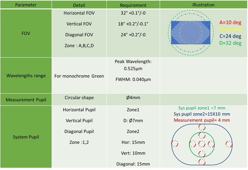
Measurement Pupil size
The measurement pupil size is the size of the aperture that is used to simulate and analyze the system performances during the design and afterwards, during the performances measurements. The aperture shall be circular and the diameter of the aperture shall be given in mm. (Several sizes may be defined, for example, the eye pupil size changes with different light intensity).
System Pupil size
System pupil is the area (located at exit pupil distance), within which the measurement pupil may lie. The system pupil size shall be given in mm, with the required accuracy, in at least three axes: vertical, horizontal and diagonal. In addition, a sketch shall be attached illustrating the system pupil shape and how the measurement pupil shifts within the system pupil. Different areas within the system pupil may be defined, in case requirements may differ in different system pupil areas (optional).
Display Field of View (DFOV)
The Display Field of View defines the angular range of the projected image from the display unit to the user’s eye. The field of view shall be given in degrees, with the required accuracy, in at least three axes: vertical, horizontal and diagonal. In addition, a sketch shall be attached illustrating the DFOV shape. Different areas within the DFOV may be defined, in case requirements may differ in different DFOV areas (optional).
Contrast Transfer Function (CTF)
These definitions along with many other terms in AR/VR optical systems are widely used, but not accurately defined, thus open for interpretations. We are working to create a full glossary of terms used in AR/VR systems based on our experience in one of the future posts.
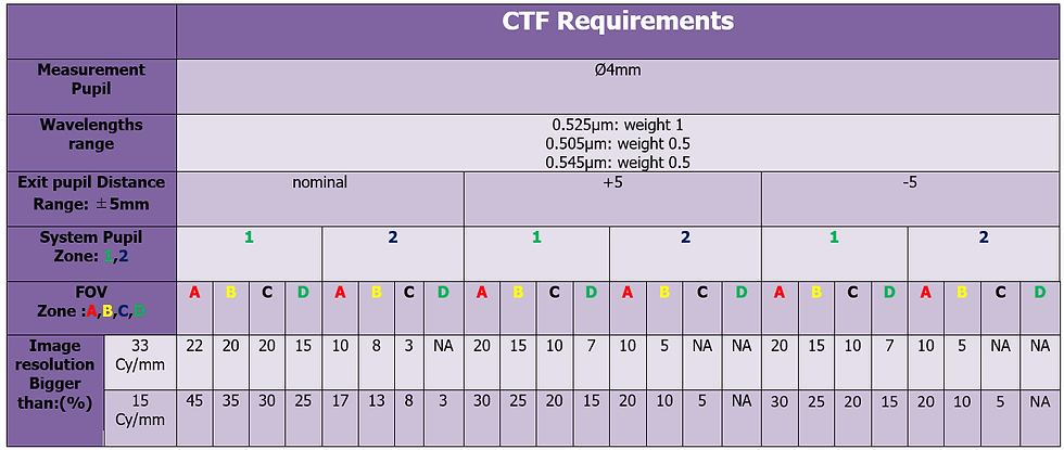
Step3: Detailed Requirements - CTF Example
Example of detailed CTF optical requirements is presented in the table below.
Only after all the terms are clear to everyone (the terms are defined once and used as needed), one can define the requirements for all the parameters. Here is an example of some requirements for AR\VR systems optical parameters.
Comments